
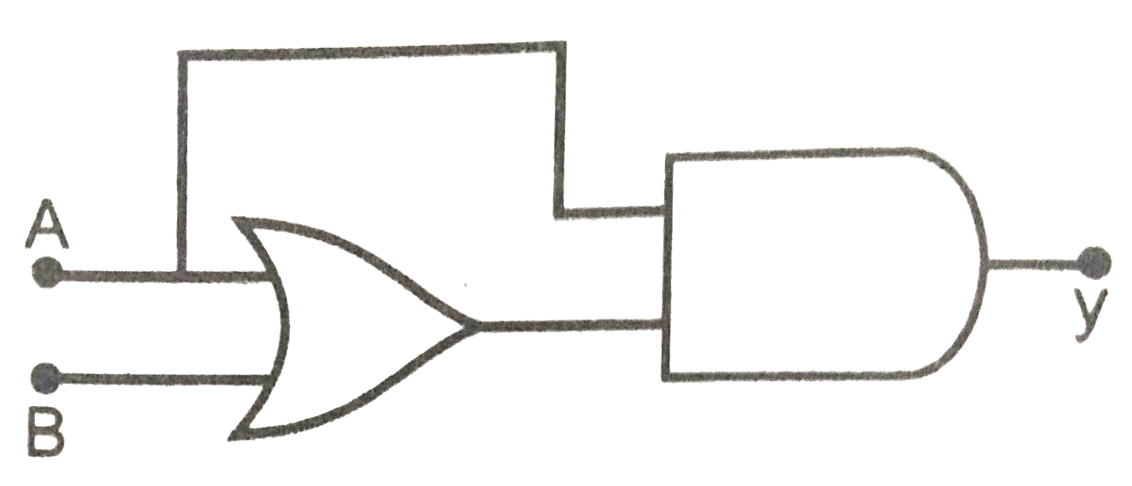
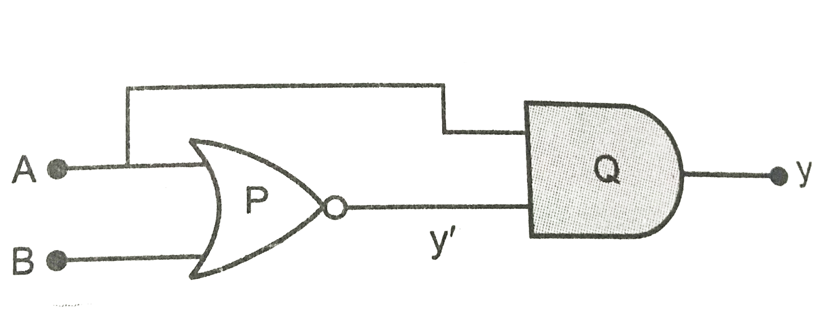
Construct the truth table for the function y of A and B represented in Fig.
Video Solution

Text Solution
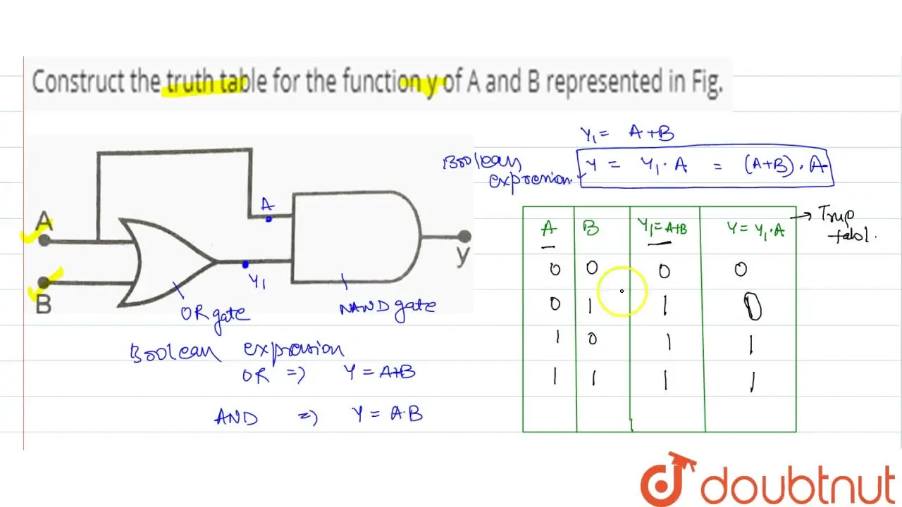
In the, given circuit we have used OR gate and AND gate. Let y′ be the output of the OR gate. Therefore A+B=y′. The AND gate receives A and y′ as input. The output of this gate is y. Therefore, y=A.y′=A.(A+B). The following table shows all the combinations of A and B related to y
∣∣
∣
∣
∣
∣
∣∣ABy'=A+By=A.(A+B)0000011010111111∣∣
∣
∣
∣
∣
∣∣
∣∣
∣
∣
∣
∣
∣∣ABy000010100111∣∣
∣
∣
∣
∣
∣∣
Thus the table is the truth of the given electronic circuit.
|
Updated on:21/07/2023
Related Playlists
- BOOK - PRADEEPCHAPTER - ELECTRONIC DEVICESEXERCISE - SAMPLE PROBLEM2videos
ELECTRONIC DEVICES
- BOOK - PRADEEPCHAPTER - ELECTRONIC DEVICESEXERCISE - CONCEPTUAL PROBLEMS1videos
ELECTRONIC DEVICES
- BOOK - PRADEEPCHAPTER - ELECTROMAGNETIC WAVESEXERCISE - II Focus multiple choice question5videos
ELECTROMAGNETIC WAVES
- BOOK - PRADEEPCHAPTER - ELECTROSTATICSEXERCISE - ASSERTION-REASON TYPE QUESTIONS2videos
ELECTROSTATICS
Similar Questions
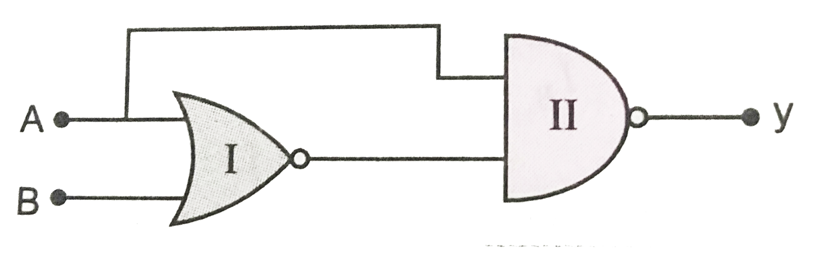
Write the Boolean expression and construct the truth table for the function y of A and B in Fig.
 View Solution
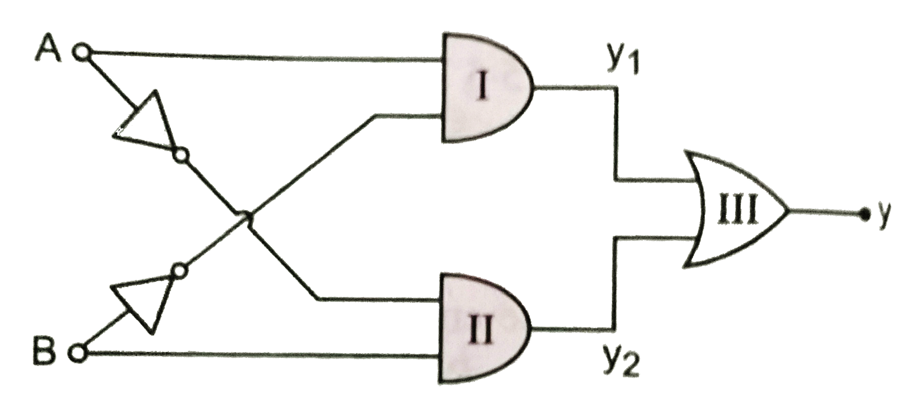
Find the truth table for the function Y of A and B represented in the following figure.
 View Solution
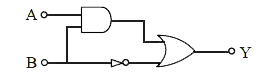
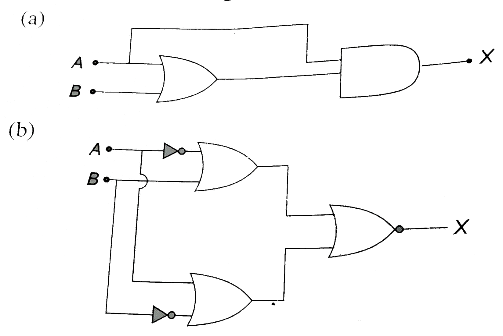
Construct truth table for the function X of A and B as shown in the figure.
 View Solution
The truth table for NOT gate is.
View Solution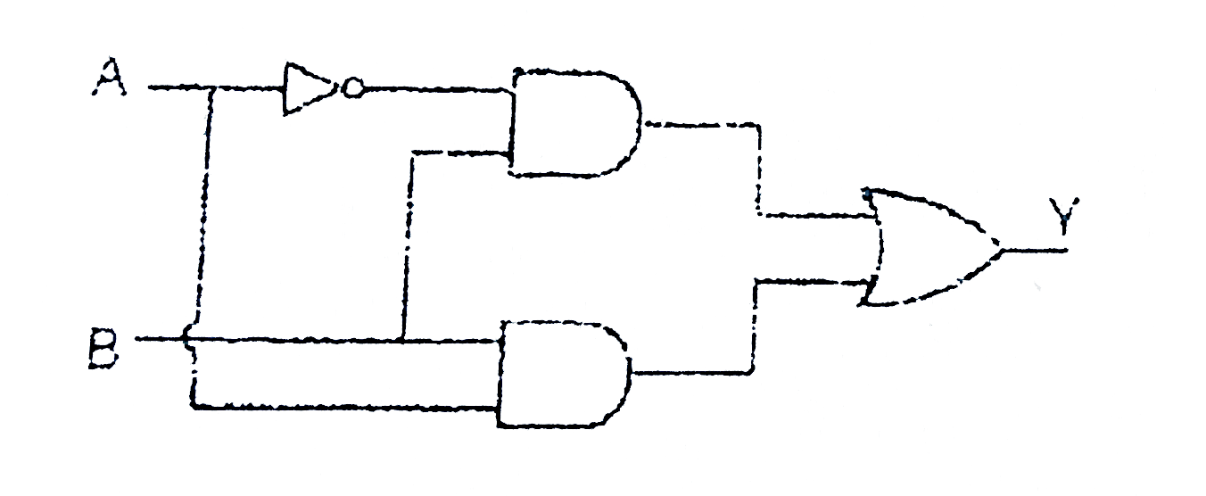
Truth table for the following is-View SolutionWrite the truth table of AND gate.
View SolutionGive the truth table for NOR gate.
View SolutionWrite the truth table for the circuit shown in Fig.
 View Solution
Write the truth table for the logical function Z=(X and Y)or X.
View SolutionWrite the truth table for the combination of the gates shown in Fig. Name the gates used.
 View Solution